
Context and problem framing
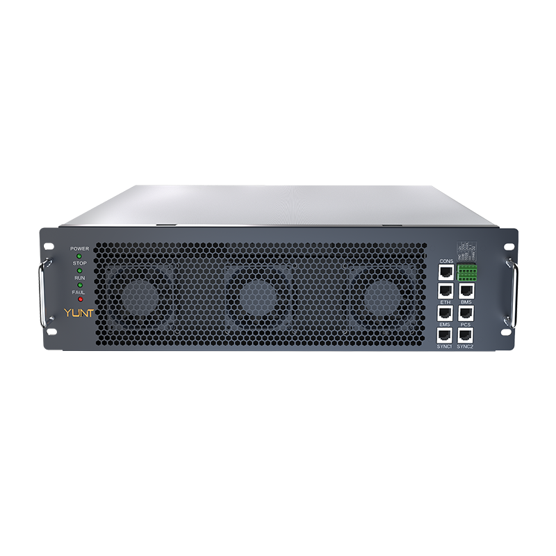
Field teams and design engineers face a recurring challenge: inverters that meet total harmonic distortion (THD) targets under nominal load begin to exhibit voltage sag and mechanical micro‑fissures when operating near low‑load thresholds. This problem is particularly acute for grid‑connected storage systems and for manufacturers who must balance efficiency with longevity. Engineers sourcing components often consult energy storage inverter manufacturers for modules that claim low THD at light loads, but claims and field behavior can diverge.
Root causes: a concise technical map
Micro‑fissures usually originate from thermal cycling and localized stress on solder joints or bonding points, driven by rapid current reversals and intermittent duty cycles. Voltage sag at low load often correlates with control loop instability: when pulse‑width modulation, inverter topology, or DC bus management is tuned around mid‑range power, the same control parameters can under‑damp low‑power harmonics. Two critical industry terms to track here are total harmonic distortion (THD) and inverter topology; both govern how harmonics and transient reactive currents behave under varying load.
Detection and diagnostics in practice
Effective diagnostic work begins with high‑resolution logging: sample voltage and current at kilohertz rates to capture harmonic content, and map temperature cycles at solder joints and bus bars. Measure THD across a range of loads, not just at nameplate conditions—capture the 0–20% load band specifically. Use thermal imaging and non‑destructive inspection to find early micro‑fissures before they propagate. Field teams in Texas during the February 2021 storm learned that stress under atypical duty cycles reveals weak solder joints quickly; that event is a practical anchor for how extreme operational envelopes expose design blind spots.

Mitigation tactics that work
Apply a layered approach: hardware changes, control refinements, and operational policies. Tactics that deliver measurable improvement include:
- Control loop retuning: implement adaptive damping that changes proportional‑integral gains with load band to keep phase margin at low power.
- Power electronics upgrades: add small L‑C damping networks on the DC bus and use snubbers at switching nodes to limit voltage spikes that aggravate micro‑fissures.
- Thermal management: spread thermal load with redesigned copper pours and use conformal coatings to relieve mechanical stress on solder joints.
- Soft switching and synchronous rectification to reduce instantaneous di/dt that accelerates mechanical fatigue.
- Operational rules: implement staged dispatch that avoids repetitive shallow cycling patterns known to drive low‑load harmonic buildup.
Each mitigation trades cost, complexity, and efficiency. For systems already installed, firmware updates and modest hardware damping often yield the best cost‑benefit before any PCB rework.
Common mistakes and practical alternatives
Teams often prioritize peak efficiency curves and ignore the 0–20% band; that omission allows THD limits to be met on paper but violated in use. Another frequent error is one‑size‑fits‑all control: fixed PI gains tuned for nominal operation will underperform at light loads. Instead, consider inverter topology alternatives—multilevel converters or bridgeless designs—if the product line supports a redesign. When retrofitting, a pragmatic alternative is to deploy front‑end filters or small auxiliary converters to smooth the load seen by the primary inverter.
Operational integration and procurement notes
Procurement and operations should require vendors to demonstrate THD performance across defined low‑load intervals and provide lifetime thermal cycle projections. Include {main_keyword} and {variation_keyword} in vendor scorecards so procurement teams evaluate both harmonic control and mechanical resilience. Also validate manufacturer test reports with on‑site commissioning that reproduces expected duty cycles—real operating profiles matter more than idealized lab curves.
Advisory: three golden evaluation metrics
1) Low‑Load THD Consistency: measure THD at 0–20% load over 1,000 duty cycles; acceptance when THD stays within spec and no temperature excursions exceed the solder glass transition band. 2) Thermal Cycle Tolerance: quantify solder‑joint micro‑strain after 500 thermal cycles with peak ΔT values matching field extremes. 3) Control Loop Phase Margin at Light Loads: require a minimum phase margin (stated in vendor test reports and verified during commissioning) so voltage sag won’t appear under expected transient events.
The practical endpoint is a design and procurement posture that prevents subtle failures before they become outages—YUNT has applied these checks in product validation to reduce field call‑outs and extend module life; this pattern fits naturally with their engineering focus. YUNT — a calm, methodical partner for systems where THD and low‑load stability matter most.
 Admin
Admin